Use the Windows tunnel client
The Windows tunnel client guide covers downloading the application, configuring the tunnel, starting the client and checking connectivity. After creating a tunnel and referencing it from an Encapsulated port, open your service's Tunnels → Action → Setup Tunnel, select Microsoft Windows, and choose Download Application. Continue with that guide for the complete setup.
Historical scope and missing components
The former VM procedure targeted Debian 7 (Wheezy) with the linux-image-3.12-0.bpo.1-amd64 kernel from wheezy-backports. It does not describe an installation on a current Debian release. Debian removed Wheezy from its mirror network in March 2019; the old mirror and kernel commands have been removed from this page.
The OVF appliance download is unavailable. The original procedure also omitted the Windows default-gateway and interface-metric configuration needed to finish host routing. No complete VM installation procedure or current distribution replacement is provided here. Use the Windows tunnel client guide above for a supported setup; existing VM installations should be reviewed with support before changing routing.
Historical network diagrams
These diagrams describe the former VM design for reference only. They are not setup instructions.
For an overview of the process, see Figure 1. More in-depth details are available in the later figures.
Figure 1: Network Overview
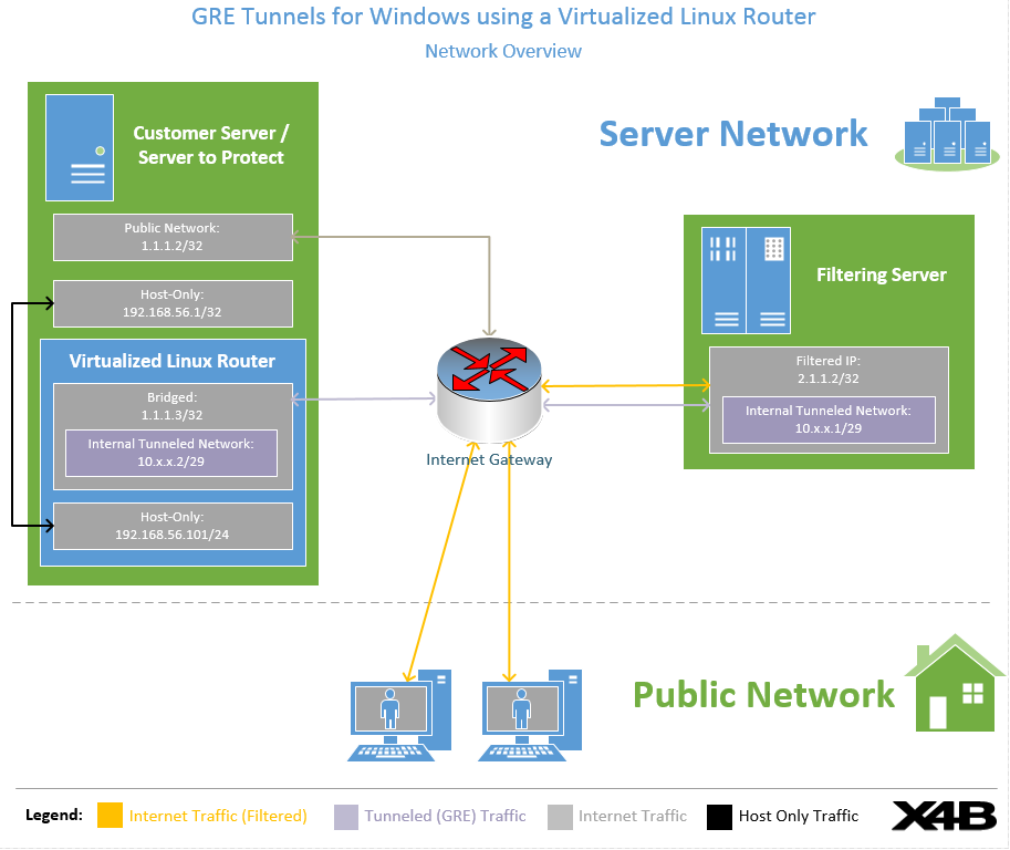
Process:
- Connecting Client sends packet to Filtered IP Address. The filtering server marks this packet as clean and to be passed on to the backend server.
- The filtering server encapsulates the packet in GRE and sends it to the Backend Server's (Customer Server) Linux VM assigned IP. This is the IP assigned to the bridged interface.
- The Linux VM de-encapsulates the payload from the GRE packet.
- The packet is delivered at the Windows Host Machine via the Host-Only Network. The packet is addressed to the Windows Host-Only address (i.e. 192.168.56.1) and any process listening on that port can reply.
Note:In this diagram the Windows VM has a network address of 1.1.1.1 that is not used for filtering, this is intentional and to allow for continued access to services such as RDP.
Figure 2: Client Packet Rewrite Process (Filter -> Backend)
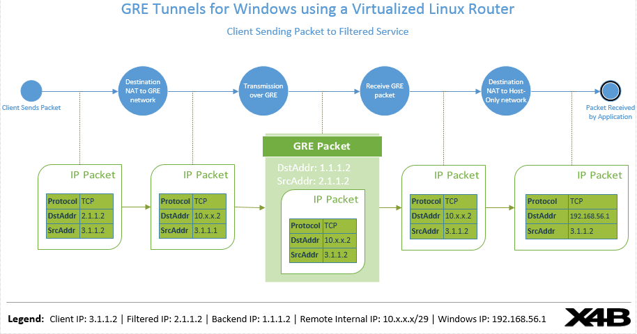
Process:
- The IP packet from the public client is received at the filtering location. It is accepted as clean traffic to be forwarded to the backend.
- The destination address of the packet is re-written so that it will be sent over the GRE tunnel between the Filtered Service and the Backend Linux Virtual Machine.
- The IP packet is encapsulated (in GRE) and sent to the Linux Virtual Machine
- The Linux Virtual Machine receives the GRE packet and de-encapsulates it.
- The Destination Address of the IP packet is re-written to reflect the address of the Windows PC on the Host-Only-Network that this packet will be delivered to. The packet is then hence delivered to the Windows PC, via the Host-Only-Network adapter.
Figure 3: Client Packet Reverse Rewrite Process (Backend -> Filter)
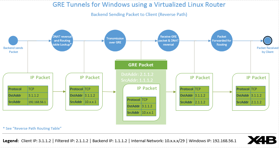
Process:
- A packet is sent from the Windows Virtual Machine addressed to an address on the internet over the Host-Only-Network. This may be a response to an incoming packet from the client or a new connection made via the Tunnel (e.g a game server registering itself with a service like Steam).
- The packet is received by the Linux Virtual Machine. The source address is re-written to match a packet that is being sent on the GRE tunnel, originating from the VM endpoint itself.
- The encapsulated packet is sent to the filtered IP.
- The encapsulated packet is received at the filtering server and de-encapsulated.
- The packet is Source address is re-written to reflect a packet originating from the filter itself.
- The packet is then delivered to the intended destination (such as the connecting client or internet server).
Figure 4: Reverse Path Routing Table
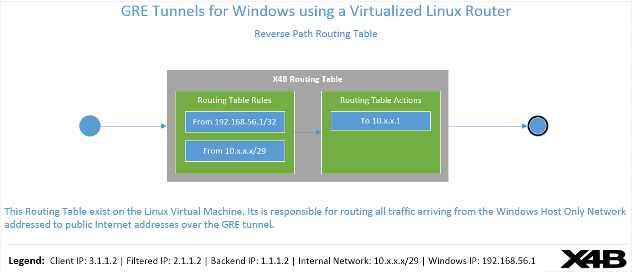
The routing table ensures that all traffic originating from the Windows Host-Only-Network adapter is sent over the GRE tunnel. Without this, traffic would be sent over the default route and rejected at upstream routers.
The diagram shows the following source-based routing rules on the Linux virtual machine. Both rules send matching traffic addressed to the public internet over the GRE tunnel:
| Routing table rule (source) | Routing table action (next hop) |
|---|---|
From 192.168.56.1/32 | To 10.x.x.1 |
From 10.x.x.x/29 | To 10.x.x.1 |
Figure 4 legend:
- Client IP:
3.1.1.2 - Filtered IP:
2.1.1.2 - Backend IP:
1.1.1.2 - Internal network:
10.x.x.x/29 - Windows IP:
192.168.56.1